Mechanical Engineering Design (MIE243)
I took a mechanical engineering design course to feed my curiosity, and expand my breadth of knowledge in the field of robotics. Whether I have to design some simple mechanical parts, or work with mechanical engineers in a robotics context, I will be well equipped.
I found the course extremely interesting. Through hands on projects, I learned how to design machines from a mechanical design perspective, and how to bring those ideas to life in CAD (Computer Aided Design) software like SolidWorks. In fact, I was able to pass the CSWA (Certified SOLIDWORKS Associate) test with flying colors, becoming SolidWorks certified.
Dissections
During the semester, we had group dissections, where we dissected existing mechanisms to better understand them. We cadded the mechanisms using SolidWorks, modified them, and analyzed their strengths and weaknesses. We also learned to make engineering drawings both by hand, and using solidworks.
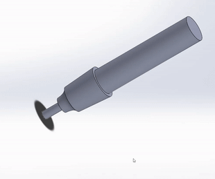
One of the assemblies I made in SolidWorks for an electric screwdriver
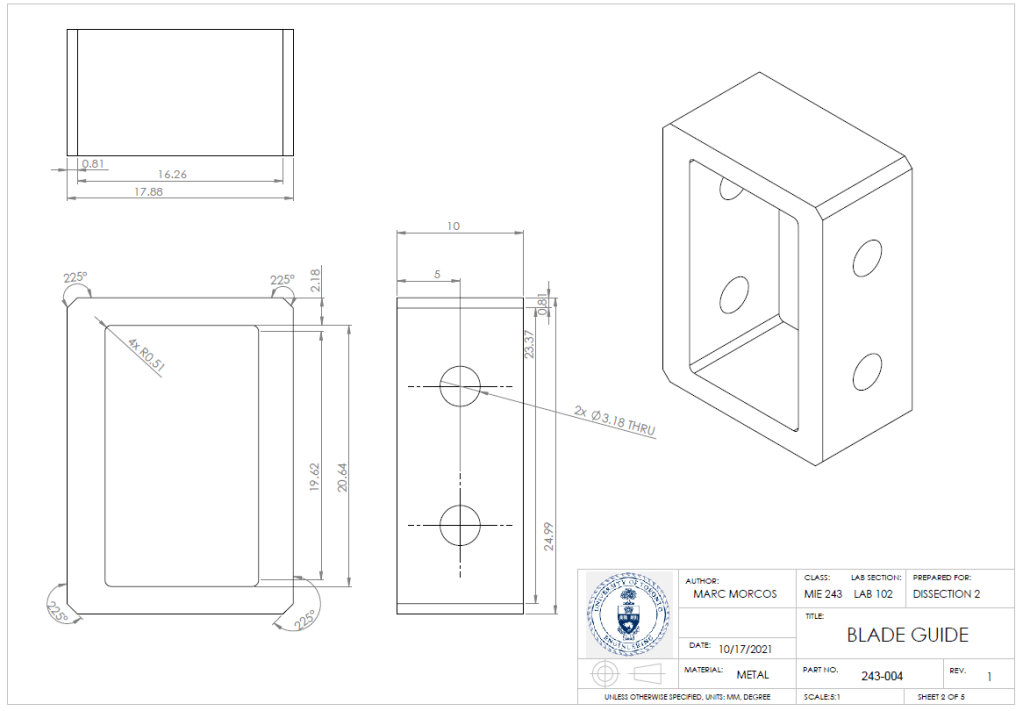
An engineering drawing I made in SolidWorks
Later in the course, we designed our own gearbox and had it 3D printed. I was well prepared for this due to my previous experience with 3D printing. We had to print our parts within a strict printing time limit. This limited the amount of material we could print. However, we were able to use this limited material to still make a relatively durable design.
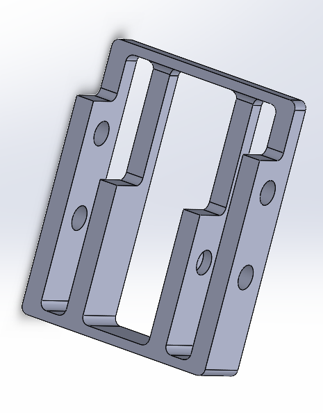
Casing Design
The final result was a simple elegant design that met all the design specification, ready weeks in advance of the deadline.
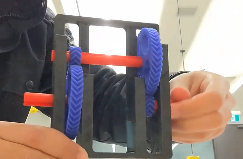
3D Printed Final Dissection Design
Designing a CNC Mill
The overarching project in this course was to design our own CNC milling machine. My team used everything we had learned in this course, from specific mechanisms to the engineering design process as a whole. Before we had learned to use SolidWorks, I used tinkerCAD to make some simple candidate designs.
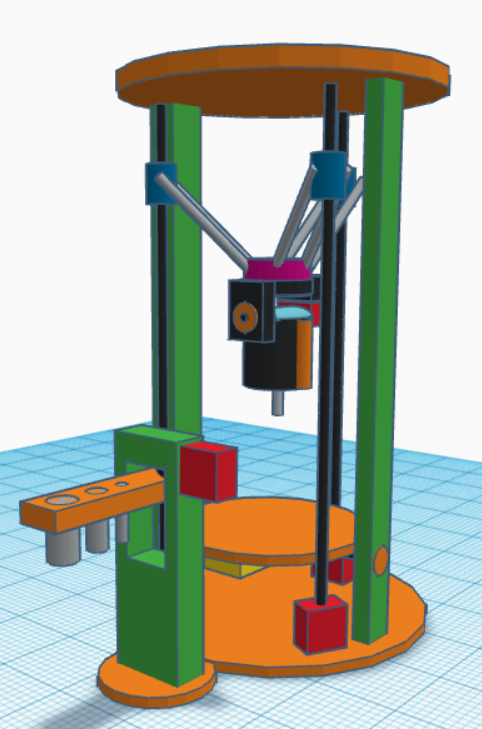
My candidate design made in tinkerCAD
After many iterations of candidate designs, as well as mechanism selection, my team was able to start creating our final design. We modelled this final design in SolidWorks, using both our own original parts, and parts supplied by manufacturer websites. I worked on multiple subsystems, including the movement axes, the frame, and the automatic tool changer.
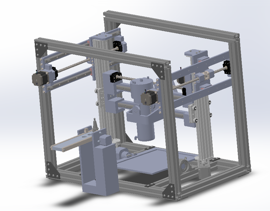
Final Assembly (with protective acrylic cover removed)
The final result was a full CAD for the CNC machine, which was thoroughly analyzed to ensure that all requirements were met and/or exceeded.